


Feedback Connector X41 (SFA, accessory)
SFA (Smart Feedback Adapter) converts conventional feedback signals to a 2-wire serial signal. SFA can be laid into the cable duct or may be mounted to a DIN rail using a standard DIN rail clip.
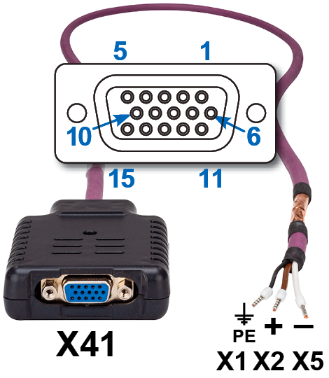
SFA provides a 15 pole HD Sub-D female connector X41 to the system for connection of a Kollmorgen motor feedback cable (see Kollmorgen 2G Cable Guide). Dimensions (LxWxD): 88.6 x 55.6 x 21.2 (28.6 with rail clip). Order codes see regional Accessories Manual.
|
|
Connect the flying leads of the SFA cable to X1 (FB1, EXX3) or X2 (FB2, EXX4) or X5 (FB2, EXX4):


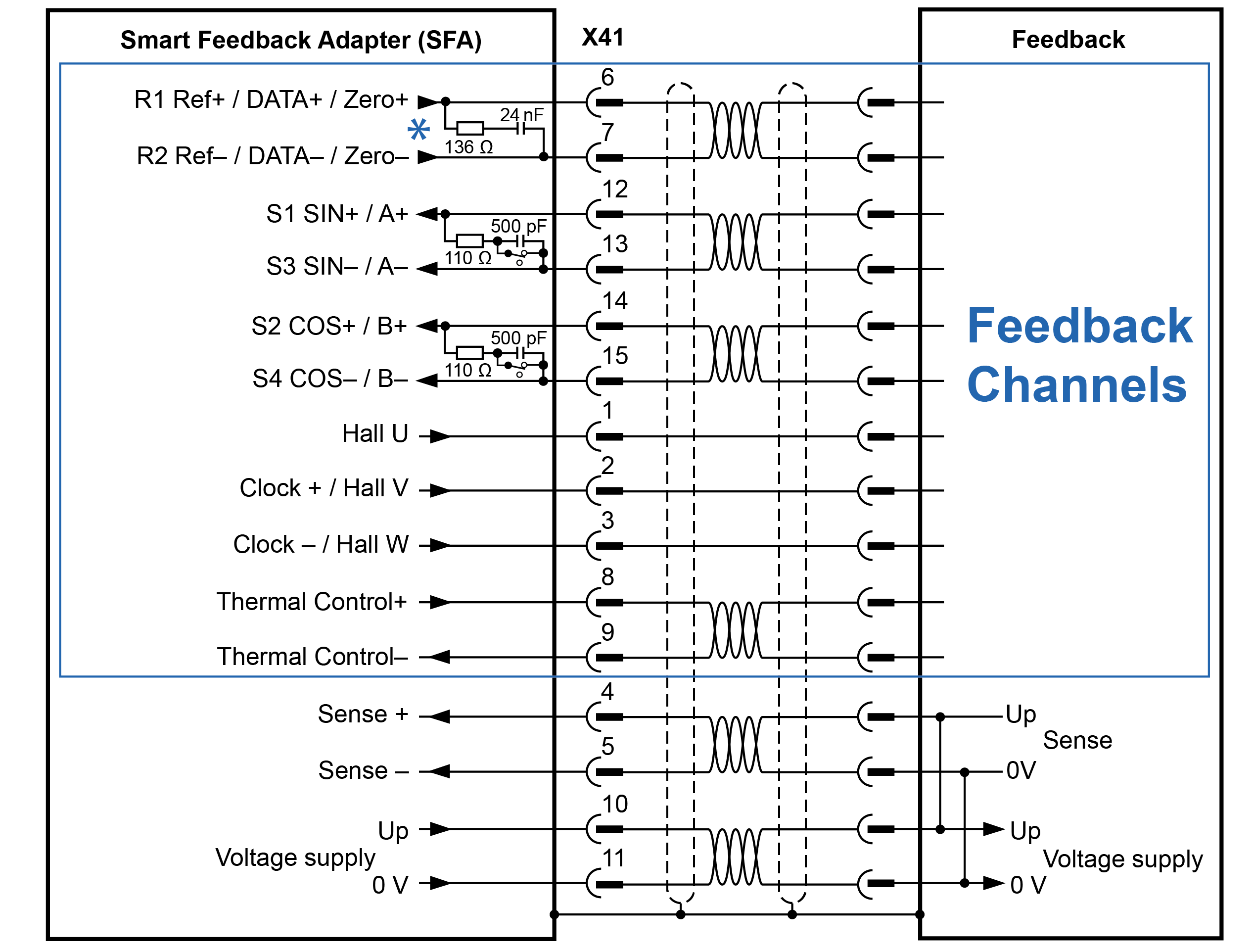
X41 Connector Pinout Summary
|
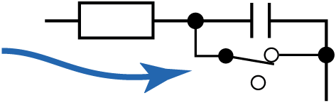
*The SFA does not include a DC termination switch across pins 6 and 7. |
|
Operating Voltage: 7 V to 12 V, max. Load Current: 350 mA
Max. A/B signal input frequency: 3 MHz
| X41 | SFD | Resolver | BiSS | EnDat | HIPERFACE | Sin / | Sin / Cos | Incr. Enc. | Incr. Enc. | Hall | SSI | ||
|---|---|---|---|---|---|---|---|---|---|---|---|---|---|
| Pin |
(1) | B | C | 2.1 | 2.2 | Cos |
+Hall |
+Hall |
|
|
|||
| 1 | - | - | - | - | - | - | - | - | Hall U | - | Hall U | Hall U | - |
| 2 | - | - | CL+ | CL+ | CL+ | CL+ | - | - | Hall V | - | Hall V | Hall V | CL+ |
| 3 | - | - | CL- | CL- | CL- | CL- | - | - | Hall W | - | Hall W | Hall W | CL- |
| 4 | S+ | - | S+ | S+ | S+ | S+ | S+ | S+ | S+ | S+ | S+ | - | - |
| 5 | S- | - | S- | S- | S- | S- | S- | S- | S- | S- | S- | - | - |
| 6 | COM+ | R1 Ref+ | D+ | D+ | D+ | D+ | D+ | Z+ | Z+ | Z+ | Z+ | - | D+ |
| 7 | COM- | R2 Ref- | D- | D- | D- | D- | D- | Z- | Z- | Z- | Z- | - | D- |
| 8 | - | Th+ | Th+ | - | Th+ | - | Th+ | Th+ | Th+ | Th+ | Th+ | Th+ | Th+ |
| 9 | - | Th- | Th- | - | Th- | - | Th- | Th- | Th- | Th- | Th- | Th- | Th- |
| 10 | +5 V | - | +5 V | +5 V | +5 V | +5 V | 8 to 9 V | +5 V | +5 V | +5 V | +5 V | +5 V | +5 V |
| 11 | 0 V | - | 0 V | 0 V | 0 V | 0 V | 0 V | 0 V | 0 V | 0 V | 0 V | 0 V | 0 V |
| 12 | - | S1 SIN+ | A+ | - | A+ | - | SIN+ | A+ | SIN+ | A+ | A+ | - | - |
| 13 | - | S3 SIN- | A- | - | A- | - | SIN- | A- | SIN- | A- | A- | - | - |
| 14 | - | S2 COS+ | B+ | - | B+ | - | COS+ | B+ | COS+ | B+ | B+ | - | - |
| 15 | - | S4 COS- | B- | - | B- | - | COS- | B- | COS- | B- | B- | - | - |
CL = CLOCK, D = DATA, S = SENSE, Th = Thermal control, Z = Zero
(1) : Resolver with AKD2G-CON-SFA-R00 only, all other feedback devices with AKD2G-CON-SFA-E00 only
█ = DC Terminated, can be overridden with "DIO#.TERM"
█ = Optional


